


A reliable battery charger is the backbone of any off-grid or backup power system, whether you’re powering an RV road trip, operating marine equipment on the water, or maintaining a home backup battery bank for power outages. Knowing how to connect a battery charger correctly is critical to ensure safe, efficient battery charging, extend battery lifespan, and avoid costly electrical damage or safety hazards.
How to connect AC-DC battery charger?
An AC-DC battery charger converts household AC power into regulated DC power that can safely recharge a compatible battery. Using the LiTime 12V 10A LiFePO₄ Battery Charger as an example, it accepts 100–240V AC input and delivers 14.6V DC at up to 10A for 12V LiFePO₄ batteries.
Before starting installation and connection, prepare matched accessories to ensure stable, safe, and polarized wiring. Using the LiTime 12V 10A LiFePO₄ Battery Charger as the standard example, safety-first steps to connect your AC-DC battery charger for RV, marine, and home backup LiFePO₄ battery systems are below:
1.Check compatibility
Match the charger’s rated voltage to your battery voltage. For LiTime 12V 10A chargers, only use compatible 12V LiFePO₄ batteries with 20–100Ah capacity to ensure safe and normal charging.
2.Inspect all equipment and accessories
Check the AC plug, DC connector, ring terminals, and cable insulation. Make sure all parts are clean, dry, and undamaged. Replace any worn or broken accessories to avoid short circuits and charging errors.
3.Connect battery terminals
Secure the red ring terminal to the battery positive (+) post and the black ring terminal to the negative (-) post. Tighten all bolts firmly and keep positive and negative cables separated to prevent short circuits.
4.Connect AC power supply
Plug the AC cable into the charger, then connect it to a standard household wall outlet, RV shore power, or marine shore power socket. Confirm stable AC power input before continuing.
5.Connect DC connector to start charging
Firmly fasten the Anderson DC connector to complete the circuit. Once all connections are correct, the charger will automatically initiate its three-stage intelligent charging process.
6.Check LED indicator status
Read the charger LED to monitor working conditions:
- Solid Red: Charging in progress
- Solid Green: Fully charged
- Flashing Green: Standby mode
- Flashing Red: Fault detected (reverse polarity, overheating, short circuit, or overvoltage)
7.Disconnect safely after charging
Follow the correct disconnection order: unplug the AC power first, disconnect the DC Anderson connector, then remove the black negative cable before the red positive cable to eliminate short-circuit hazards.
How to connect DC-DC battery charger?
A DC-DC battery charger uses power from a vehicle’s alternator and starter battery to charge a secondary battery, also called a house or service battery. It regulates the incoming DC power and applies the correct charging profile for the selected battery type.
Using the LiTime 12V 40A DC-DC Battery Charger as an example, the charger operates in a 12V system and supports LFP, AGM, GEL, and standard lead-acid batteries. It normally provides up to 40A charging current, while the optional low-current connection can limit the current to 20A.
Install the charger close to the house battery in a cool, dry, and well-ventilated location. Leave at least 2 inches or 5 cm of clearance around it and secure the unit firmly. Disconnect the batteries before starting the wiring work.

Steps to Connect the DC-DC Battery Charger:
1.Prepare the cables
Prepare two positive and two negative battery cables with correctly sized M8 ring terminals. Keep the red positive and black negative cables clearly identified.
2.Connect the house battery first
Connect the charger’s output positive terminal to the house battery’s positive terminal. Connect the output negative terminal to the house battery’s negative terminal. Install the recommended fuse or breaker in the positive output cable.
3.Select the correct battery type
Turn the mode selector knob to match the house battery:
- LFP for LiFePO₄ batteries
- AGM for AGM batteries
- GEL for gel batteries
- STD for standard lead-acid batteries
The house battery must be connected and the correct battery type selected before connecting the starter-battery input.
5.Connect the starter battery
Connect the charger’s input positive terminal to the starter battery’s positive terminal through the recommended fuse or breaker. Connect the input negative terminal to the starter battery’s negative terminal.
6.Connect the power-on signal cable
Use the supplied signal cable to connect the D+ port to the adjacent IN+ port. This connection is required to turn on this LiTime DC-DC charger.
7.Set the optional 20A charging mode
For a lower charging current, connect the LC port to the adjacent IN+ port with the second signal cable. This limits the charger to 20A. Leave this connection unused when the full 40A charging current is required.
8.Check the complete wiring
Confirm that all positive and negative connections are correct, all terminal bolts are tight, and the cables cannot contact moving or hot vehicle components.
9.Start the vehicle and check the charger
After completing the installation, start the engine so the alternator can supply power. The fault LED should remain off during normal operation. If it turns on, check for incorrect polarity, abnormal voltage, overheating, a short circuit, or a loose connection.
Do not disconnect cables while the charger is operating. Turn off the vehicle and isolate the batteries before changing the wiring.
How to connect Inverter + battery charger 2-in-1?
An inverter charger combines an inverter and an AC battery charger in one unit:
- In inverter mode, it converts battery DC power into AC power for RV appliances.
- In charging mode, it converts AC power from shore power or a generator into regulated DC power to recharge the battery bank.
- When AC power is available, it can also supply connected loads while charging the battery.
Using the LiTime 12V 3000W Pure Sine Wave Inverter Charger as an example, the unit is designed for a 12V battery system, provides 3000W of continuous pure sine wave AC output, and supports an adjustable charging current from 5A to 45A. It supports several battery types, including LiFePO₄, AGM, SLA, gel, and open lead-acid batteries.
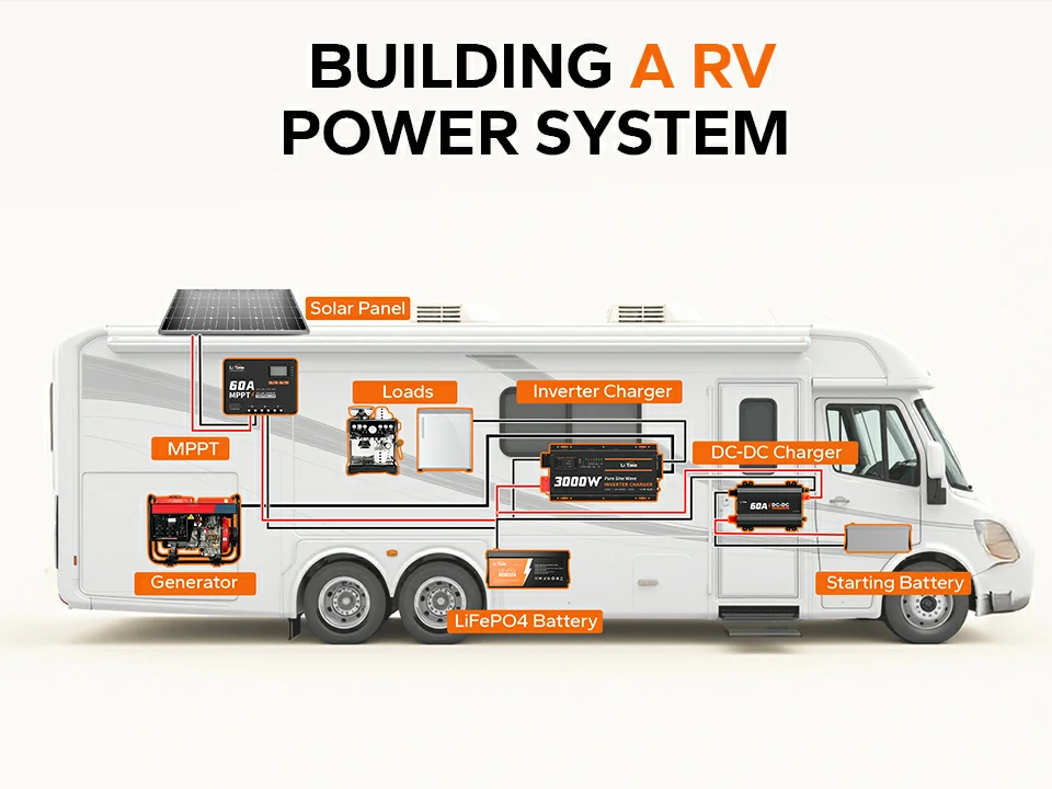
Steps to Connect the Inverter Charger:
1.Choose the installation location
Install the unit close to the battery bank in a cool, dry, and well-ventilated location. Keep approximately 12 inches of clearance around the AC and DC sides. Horizontal installation is recommended for better cooling.
2.Keep all power sources off
Place the inverter charger’s power switch in the OFF position. Turn off the battery fuse or breaker, AC input breaker, generator, shore power, and connected loads.
3.Ground the inverter charger
Connect the grounding terminal to an approved ground point or the RV’s bare-metal chassis using a properly sized grounding cable. The connection must be tight and made against clean, bare metal.
4.Connect the battery bank
Remove the DC terminal covers. Connect the battery’s positive terminal to the inverter charger’s positive terminal and the battery’s negative terminal to its negative terminal. Install the required fuse or breaker close to the battery on the positive cable, and then reinstall the terminal covers. This model must only be connected to a 12V battery bank.
5.Connect the AC input
Keep the shore-power or generator source switched off. Remove the AC terminal-block cover and connect the AC input conductors to the indicated Ground, Live, and Neutral terminals. Secure the wires and reinstall the cover.
6.Connect the AC loads when required
Connect the AC output terminal block to the RV load circuit. The built-in AC outlet is intended for loads with continuous power no higher than 1000W, while the AC output terminal block supports the unit’s full rated output when correctly installed. Never connect the AC output directly to a distribution panel that is simultaneously energized by another AC source.
7.Select the battery type
Set the battery-selection knob to match the connected battery. Choose the LiFePO₄ setting for a LiFePO₄ battery bank rather than relying on an unsuitable charging profile.
8.Set the charging current
Adjust the charging-current knob according to the battery manufacturer’s recommended charging current. The LiTime unit allows adjustment from 5A to 45A. Higher current charges faster but must remain within the battery bank’s permitted charging limit.
9.Set the operating priority
Use the DIP switch to select grid-first or inverter/battery-first operation. Grid-first mode is generally suitable when shore or generator power should supply the loads and charge the battery whenever AC power is available.
10.Power on the system
After checking polarity, grounding, fuse ratings, and terminal tightness, turn on the battery breaker, energize the AC input, and switch the inverter charger to ON. When valid AC power is detected, the charger converts the AC input into DC power and begins charging the battery.
11.Check the operating status
Use the remote display to check AC input, battery voltage, charging status, output voltage, and load level. In grid mode, the display should show AC input supplying the system and the battery being charged.
How to connect Inverter + controller + battery charger 3-in-1?
A 3-in-1 solar inverter charger combines three devices in one unit:
- A pure sine wave inverter that converts battery DC power into AC power for appliances.
- An MPPT solar charge controller that regulates solar-panel power to charge the battery.
- An AC battery charger that uses grid or generator power to charge the battery.
Using the LiTime 24V 3000W Solar Inverter Charger as an example, it integrates a 3000W inverter, a 60A MPPT controller, and a 50A AC charger. It is designed for a 24V battery bank, supports up to 1600W of solar input, and allows a maximum combined PV and AC charging current of 110A.
This design allows the battery to be charged from solar power, grid power, or a generator while also supplying AC loads. Charging and output priorities can be configured according to the application.

Steps to Connect the solar Inverter Charger:
1.Choose a suitable installation location
Install the unit close to the battery bank in a cool, dry, and well-ventilated location. Leave at least 12 inches or 30 cm of space for ventilation and wiring, and mount the unit securely.
2.Turn off all power sources
Set the inverter charger’s power switch to OFF. Confirm that the battery breaker, PV breaker, AC input breaker, AC output breaker, generator, and connected loads are all switched off.
3.Connect the battery bank first
Prepare the battery cables with the supplied connectors and heat-shrink tubing. Connect the battery positive terminal to the inverter charger’s positive battery terminal and the battery negative terminal to the negative terminal. Install the 200A breaker or fuse on the positive battery cable.
4.Connect the AC charging input
Connect either grid power or a generator to the AC input terminals in the following order:
Ground → Live → Neutral
Keep the AC source switched off while wiring. Do not connect grid power and generator power to the unit simultaneously.
5.Connect the AC output to the loads
Connect the AC output terminals to the load distribution circuit using the Ground, Live, and Neutral terminals. Do not connect the output to a circuit that is simultaneously energized by another AC source.
6.Connect the solar panels
Connect the solar positive cable to the positive PV terminal and the solar negative cable to the negative PV terminal. Connect the other ends to the solar panels using the MC4 connectors. Verify the solar array’s open-circuit voltage before switching on the PV breaker.
7.Connect optional communication cables
When a protocol-compatible battery is used, connect the RS485 communication cable pin-to-pin. Dry-contact terminals may also be connected to compatible external control equipment when required.
8.Select the correct battery type
Use the LCD settings to select the battery chemistry. Choose LFP for a compatible 24V LiFePO₄ battery bank. Other available modes include sealed lead-acid, GEL, flooded lead-acid, and user-defined settings.
9.Select the charging mode
The unit provides three charging modes:
- CSO – MPPT First: Solar charges the battery first; grid charging starts when solar charging is unavailable.
- CUT – MPPT and Grid: Solar is prioritized, and grid power supplements charging when solar energy is insufficient. This is the default mode.
- OSO – Only MPPT: Only solar power charges the battery.
Choose the mode according to the available power sources and required backup strategy.
10.Power on the system in the correct order
After checking polarity, cable sizes, breakers, and terminal tightness, switch on the system in this order:
Battery breaker → inverter charger switch → PV breaker → AC input breaker → AC output breaker → AC loads
This order allows the inverter charger to establish the battery connection before receiving solar or AC charging power.
11.Check the charging status
The LCD screen can display battery voltage, state of charge, charging current, PV voltage, MPPT current, AC input, output load, and operating mode.
- Yellow charge light flashing: the battery is charging.
- Yellow charge light steady: charging is complete.
- Green output light steady: grid power is operating.
- Green output light flashing: the inverter is operating.
- Red fault light: the system has detected a fault.
FAQs
Do you connect the black or the red first?
For all battery chargers, the universal safe rule is: connect the red positive wire first, then the black negative wire during installation. When disconnecting the charger, reverse the order: remove the black negative wire first, then the red positive wire.
Why won’t my battery charger detect or charge the battery?
Loose connections, incompatible voltage or battery chemistry, a deeply discharged battery, or BMS protection may prevent charging. Check the wiring, charger settings, and battery voltage.
Which wire is positive on a battery charger?
Red wires are always positive (+), and black wires are always negative (-).
What happens if I hook my battery charger up backwards?
Reverse polarity may trigger protection or blow a fuse. Without proper protection, it can cause sparks or damage the charger and battery, so disconnect it immediately and reconnect the terminals correctly.

